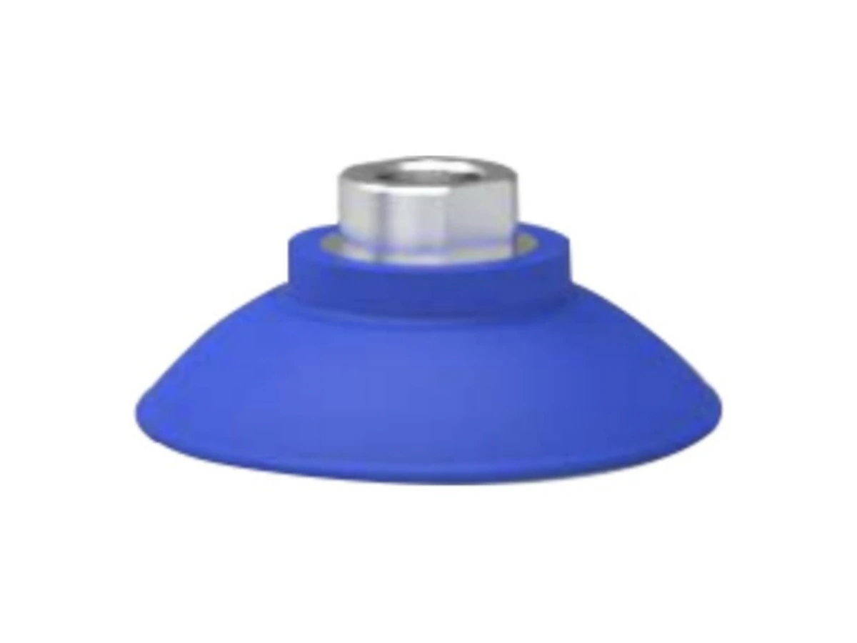
MAF Series Vacuum Suction Cups
Review flat NBR cups listed for metal-sheet handling. Compare cup sizes and thread or adapter drawings with your available contact and mounting space.
View Product & Request a QuoteApplication & component selection
For equipment builders and automation buyers, a sheet handling inquiry starts with the actual plate and its available contact areas. Compare vacuum cup geometry, mounting interfaces and motion requirements before choosing components for pickup and placement.
01 / Requirements
Identify the sheet material, thickness, dimensions and mass, then mark the regions where contact is permitted. Include holes, bends, ribs, coatings and any unsupported areas near the proposed pickup points. Record whether the sheet is handled individually or presented in a stack, and how it is supported at pickup and placement.
Surface conditions need their own description. Note oil residue, dust, protective film, curvature and variation between parts. A cup that can contact one flat area may not fit another area of the same sheet. Share the condition at pickup rather than describing the workpiece only as steel or aluminum.
02 / Requirements
MAF is a flat NBR suction cup series with metal-sheet handling references, multiple cup sizes and several connection forms. Start with the usable contact area, then compare the selected size and connection with the MAF model guide and dimensional drawings. Its component data should be reviewed alongside the actual orientation and motion of the sheet.
SBP provides a polyurethane bellows cup reference whose listed applications include sheet metal and smooth steel plate. Use it as a separate geometry option to investigate, not as an automatic substitute for MAF. Review the cup profile, space available around the contact point and the required connection for each candidate.
03 / Requirements
State whether the sheet stays horizontal, is tilted or is transferred in another orientation. Include the pickup path, acceleration requirements, placement conditions and the location of the proposed cups. The number and arrangement of contact points need review with the workpiece and movement, rather than selection from sheet mass alone.
Use the mounting drawings to check cup connections, frame space and hose routing. PEP profile references support discussion of the EOAT frame layout. VT generator references support discussion of vacuum and supply requirements. Confirm the connections and operating conditions for the proposed arrangement before treating the components as a complete assembly.
Use this checklist to connect the workpiece requirements with the appropriate component references.
| Selection topic | Workpiece or equipment input | Reference to review | RFQ question |
|---|---|---|---|
| Contact area | Flat areas, holes, curvature and restricted surfaces | MAF size and profile; SBP geometry | Which areas can support the proposed contact arrangement? |
| Surface condition | Oil residue, coating, film, dust and variation | Selected cup material and actual workpiece conditions | What surface conditions must the selection account for? |
| Orientation and motion | Pickup position, tilting, transfer and placement | Cup arrangement and complete tool layout | What movement and holding requirements need review? |
| Cup connection | Thread or adapter and available installation space | Size-specific connection drawings | Which connection matches the proposed mounting interface? |
| Frame and routing | Tool envelope, mounting points and hose paths | PEP sections and component dimensions | How will the cups and vacuum connections be positioned? |
| Vacuum and release | Available supply, source, control and release needs | VT configuration and engineering references | What vacuum-source and control information is available? |
On smaller screens, scroll the comparison table horizontally.
Compare HNQ products using their model guides and engineering drawings. Shortlist candidates for an RFQ, then confirm interfaces and application suitability before ordering.
Review flat NBR cups listed for metal-sheet handling. Compare cup sizes and thread or adapter drawings with your available contact and mounting space.
View Product & Request a Quote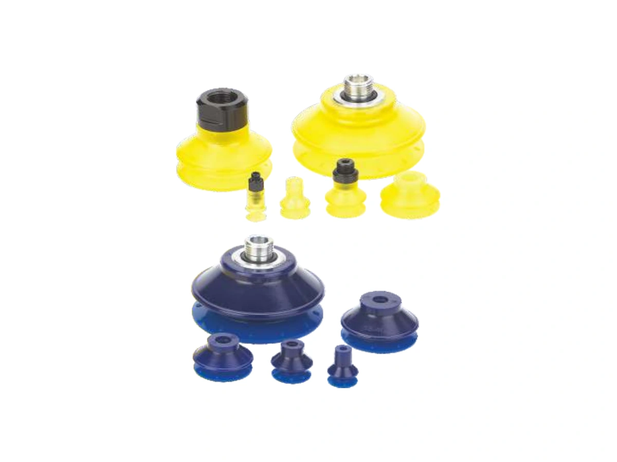
Explore the polyurethane bellows cup reference for sheet metal and smooth steel plate. Compare its geometry and connections with the workpiece requirements.
View Product & Request a Quote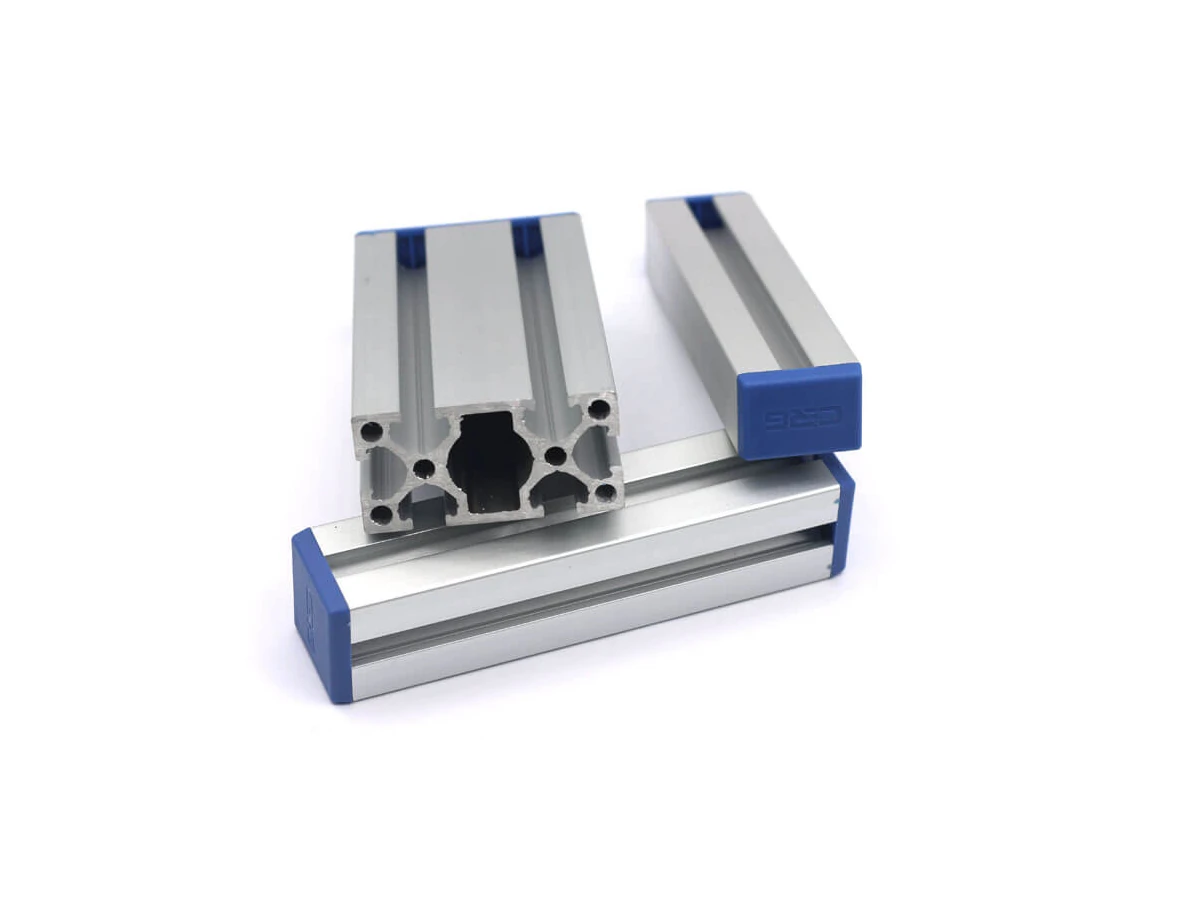
Review PEP profile sections and dimensions for the tool frame layout. Use the drawings to discuss mounting positions and connection space.
View Product & Request a Quote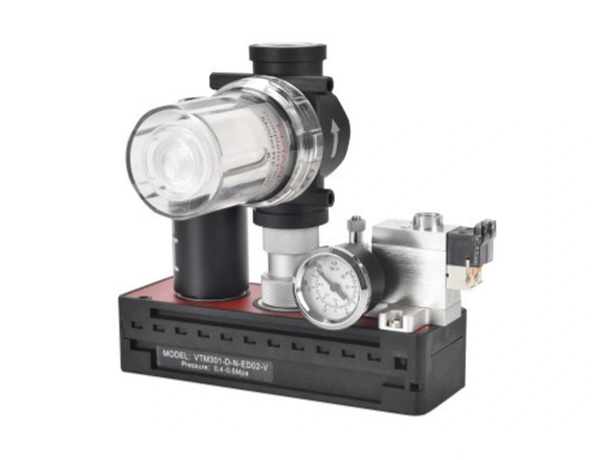
Compare VT vacuum-generator configurations and their engineering data with the available air supply and proposed vacuum arrangement.
View Product & Request a QuoteApplication RFQ
Shortlist a cup or mounting component from its product page, or describe the sheet handling task if the configuration is not yet selected. Include the contact layout and surface conditions in your message.
Include these details in your inquiry message. Leave unknown values or part numbers open for confirmation. Mention available drawings and ask how to share them; the form has no file-upload function.
Kunshan Haonaiqi Automation Technology Co., Ltd supplies industrial automation components and supports selection and quotation inquiries. This guide covers vacuum cups, mounting and vacuum-source references for sheet handling. Complete handling-system design and verification remain separate from component selection.
Start with the usable contact area, surface geometry and installation space. MAF provides a flat-cup reference for metal sheets; SBP provides a bellows reference that lists sheet metal. Compare the selected configurations and drawings with your workpiece and motion requirements.
A component value does not establish the capacity of the complete tool. The contact arrangement, sheet condition, orientation, movement, vacuum supply and mounting all need review for the task.
Describe the residue and its variation, the intended contact areas and the orientation during movement. Include any acceptance requirements for marks or movement at the contact point so the application can be assessed using the selected cup reference.
Yes. Use the Contact form to describe the sheet, surface, contact areas and handling task. If you have candidate components, add them to the RFQ list with the known quantities and note which connection or model choices remain open.