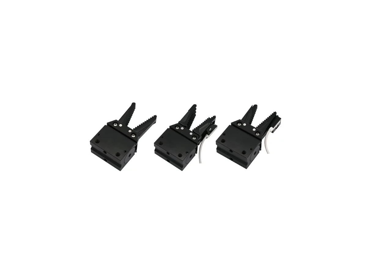
GRA20 Sprue Grippers
Explore GRA20 sprue grippers for runner handling. Compare gripping geometry and mounting drawings; confirm finished-part suitability separately.
View Product & Request a QuoteApplication & component selection
A molded part and its sprue or runner can need different contact points, gripping clearances and release arrangements. Define each handling task before choosing the gripper, tool interface and mounting components.
01 / Requirements
For the molded part, identify where contact is permitted and whether the finished surface can tolerate jaw contact. Record the part orientation at pickup, any restricted contact areas and the required placement position. A runner gripping reference does not establish suitability for gripping the finished part.
For the sprue or runner, identify the available gripping section, its geometry and the clearance around it. Review GRA20 sprue grippers against the runner contact and mounting requirements. Finished-part gripping needs its own assessment; a runner gripper is not suitable for every molded part.
02 / Requirements
Compare the candidate jaw geometry with the accessible gripping section. Allow for the space needed to approach, close, move away and release. Part mass alone is not enough to choose a gripper: contact position, orientation, motion and the available installation envelope also need review.
Use the applicable model and dimensional references to check the component arrangement. Material and temperature suitability must be confirmed for the selected configuration. This guide does not calculate gripping force or certify a grip on a particular part.
03 / Requirements
The EOAT frame needs to position the gripping components within the available mold and robot-tool space. PEP extruded aluminum profiles provide section, length and dimensional references for planning the frame. The assembled structure still requires a review of connections, tool mass, center of gravity and the actual task.
Where tool changing is required, review the robot-side and gripper-side components together. QCA-15 provides matched-side and sensor-variant references. Confirm the mounting interface, air connections and sensor/control requirements for the selected pair. A robot brand name or a catalog payload figure does not establish that the complete tool is compatible.
Use separate answers for the molded part and the runner where their requirements differ. Unknown values can remain open in the inquiry.
| Requirement | Molded part | Sprue / runner | What to confirm |
|---|---|---|---|
| Workpiece and geometry | Finished-part drawing, mass and orientation | Gripping-section shape and location | Which item is held at each stage |
| Pickup temperature | Actual temperature at the contact area | Actual temperature at the runner grip | Material and selected component suitability |
| Contact points | Permitted contact areas and surface restrictions | Accessible runner gripping section | Jaw/contact arrangement for each item |
| Gripping space | Approach, closing and release clearance | Clearance around runner and adjacent features | Component dimensions and interference |
| Motion and release | Orientation changes and placement needs | Removal path and release destination | Dynamic requirements, not just static mass |
| Mounting and changeover | Frame layout and tool envelope | Relative runner-gripper position | Mechanical interfaces and structural review |
| Air and detection | Available supply and detection requirements | Required gripping-state detection | Ports, sensor output and control interfaces |
On smaller screens, scroll the comparison table horizontally.
Compare HNQ products using their model guides and engineering drawings. Shortlist candidates for an RFQ, then confirm interfaces and application suitability before ordering.
Explore GRA20 sprue grippers for runner handling. Compare gripping geometry and mounting drawings; confirm finished-part suitability separately.
View Product & Request a Quote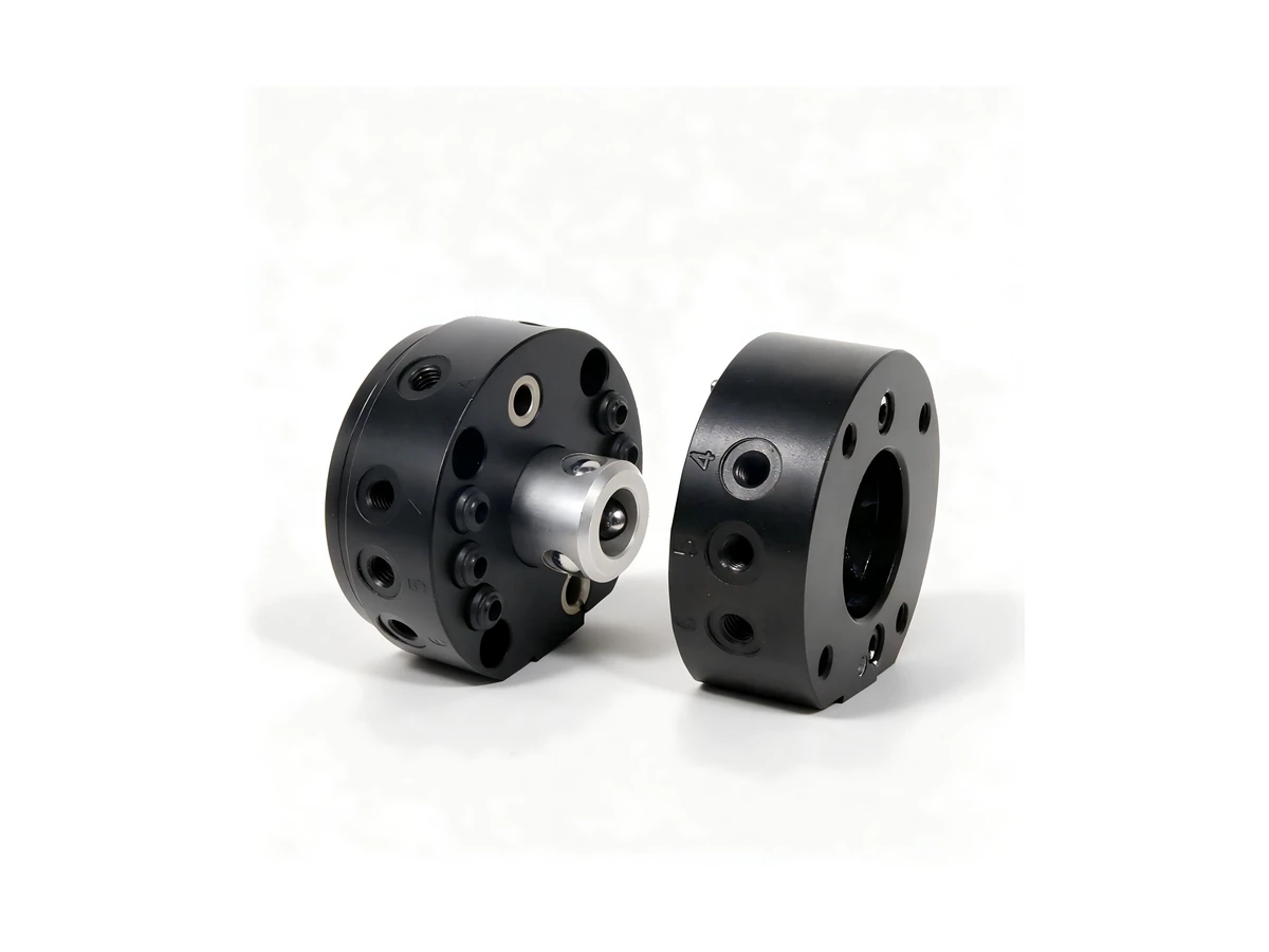
Review QCA-15 robot-side and gripper-side tool changers, mounting dimensions and sensor variants. Confirm the required interfaces before ordering.
View Product & Request a Quote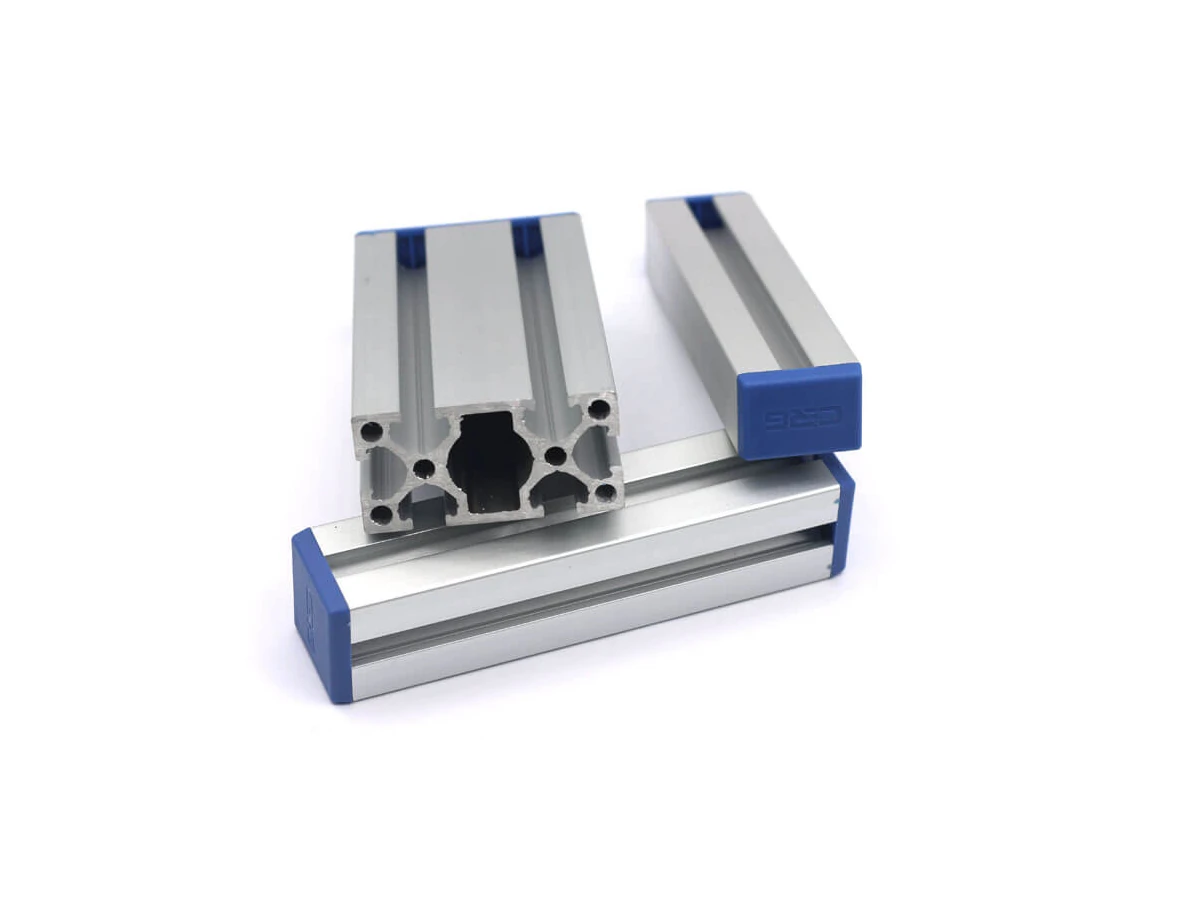
Compare PEP aluminum profile sections for your EOAT frame. Review connections and structural requirements for the actual assembly.
View Product & Request a QuoteApplication RFQ
If you already have a candidate model, open its product page and use Add to RFQ. If the model is unknown, describe the part and runner requirements in the existing Contact form message.
Include these details in your inquiry message. Leave unknown values or part numbers open for confirmation. Mention available drawings and ask how to share them; the form has no file-upload function.
Kunshan Haonaiqi Automation Technology Co., Ltd supplies industrial automation components and supports product-selection and quotation inquiries. This guide focuses on gripping, mounting and tool-changing components for injection molding applications. Cutting operations and complete robotic-cell design are outside the scope of this guide.
Not by default. Review the runner gripping section separately from the finished part, including contact restrictions, temperature and available space. GRA20 is presented here as a runner/sprue gripping reference, not a universal molded-part recommendation.
Describe the part and runner geometry, intended contact points, clearance, actual pickup temperature and motion. Include a drawing reference in the message and identify unknown items. A model or part number does not need to be invented to start an inquiry.
The robot-side and gripper-side components, mechanical dimensions, air connections and sensor/control requirements need confirmation. Neither the robot brand nor a single catalog rating establishes compatibility with the complete tool.
No. The profile page provides component dimensions and selection references. Frame connections, tool mass, center of gravity and the actual handling motion must be reviewed for the assembly.